Trident A-Range 500EQ

Sale price$ 799.99
SKU: A-Range 500EQ

Call us at 1-877-223-8858 or Ask a Question below

Trident A-Range 500EQ

Model

Trident A-Range 500EQ

The legendary A-Range® equalizer holds a unique place in audio history, with a stunningly musical sound that resulted from its all-discrete transistor circuitry and the use of inductors in the upper and lower mid bands. The A-Range® is a faithful re-creation of the original four band Trident A-Range® equalizer in a 500 module format, that will add the unique Trident signature to any programme material.

opens in a new windowDownload the A-Range® 500 User Manual here.opens pdf file

Introduction

The legendary A-Range® equaliser holds a unique place in audio history, with a stunningly musical sound that resulted from its all-discrete transistor circuitry and the use of inductors in the upper and lower mid bands. The A-Range® s a faithful re-creation of the original four band Trident A-Range® equaliser in a 500 module format, that will add the unique Trident signature to any programme material.

The mid frequency EQ sections are “peaking”, while the high and low frequency sections are “shelving”. A distinguishing feature of both the original A-Range® console and this module, is the use of faders for level adjustment, rather than rotary potentiometers. These faders feature a useful centre detent at mid travel to denote zero boost or cut of the selected frequency. The use of faders makes it very easy to see not only how much equalisation is being applied. Each band is rotary-switch-selectable to one of four frequencies, while individual push buttons engage the three high pass and three low pass filters. An LED peak level indicator is included to warn when levels get too high. The Line level input and output are balanced for maximum signal integrity & high output levels with minimum distortion.

The difference between shelving and peaking equalisers are as follows. A shelving equaliser boosts or cuts all frequencies equally, above or below a certain frequency, usually the point where it effectively reaches its “shelf” state. A “high shelf” EQ boosts or cuts high frequencies and a “low shelf” type boosts or cuts low frequencies. This type of circuit is very popular in hi-fi systems but is also actually highly musical when applied in a recording environment. In contrast, a peaking equaliser is one that, as its name implies, has a centre frequency that is boosted or attenuated more than others. The frequency range over which it reaches its peak and then falls down is known as the bandwidth (or “Q”). Because this type of design reaches a peak and then falls away, it is possible with this type of circuit to “home in” on particular frequencies and make adjustments without affecting those around them. This can be particularly useful when working with instruments such as bass guitars and snare drums. By incorporating both shelving and peaking equalisers into the design of the versatile A-Range®, it is possible to get the best of both types of design.

Operating The Equaliser

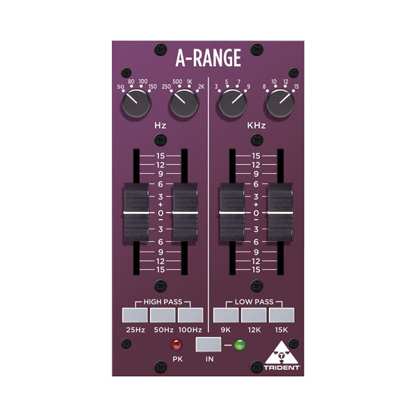
Begin with all boost/cut faders set to their mid way (‘0’) positions. Adjust the low and high mid frequency controls to their minimum positions (fully anticlockwise). The high and low pass filter switches should be in their out positions. Set the frequency select switches controlling the high and low shelving sections, to 150Hz and 12kHz respectively. Lastly,press the ‘IN’ switch (the associated green LED will light).

Pushing up any of the four faders beneath its associated frequency select switch, will result in the chosen frequency being boosted. Moving the faders below centre will result in the chosen frequency being cut. Operating the frequency select switch in the high section (8kHz to 15kHz shelving) will introduce a subtle change of emphasis. Operating the frequency select switch in the upper mid section (3kHz to 9kHz peaking) will introduce a distinct difference according to the frequency selected, since it is now peaking rather than shelving and also due to the characteristics of the inductor-based circuitry. Operating the frequency select switch in the ‘lower mid’ section, 250Hz to 2kHz peaking, will also introduce a distinct difference according to the frequency selected, again because of its peaking nature and the use of inductors in this part of the circuit.

Operating the frequency select switch in the low section, 80Hz to 150Hz shelving, will introduce an effective change of emphasis to the low frequencies.

Finally, the three shelving ‘low-pass’ and ‘high-pass’ filter sections are employed to introduce a roll-off of either high frequencies or low frequencies respectively, according to which of the three push buttons are selected in each section. The high-pass filters are useful for the minimization of extraneous low frequency ‘rumble’ caused, for example, by someone’s feet moving about near a microphone stand, nearby traffic noise, AC systems, etc. Additionally, a high-pass filter can be used effectively during recording to reduce the accumulation of low frequency sounds that can adversely affect a mix. The three high-pass corner frequencies are 25Hz, 50Hz and 100Hz. The low-pass filters are used to minimize high frequency noise that may cause ‘harshness’ in a vocal, or to tame the output of a violin or guitar amplifier, etc. Low-pass filtering is often employed on kick and snare drums and bass guitars, as well as a means of reducing ‘hiss’. The three lowpass filter frequencies on the A-Range® are 9k, 12k and 15k. Filters can also be used in combination for greater effect.

The amount of boost or cut required for any particular programme material is a very subjective matter and is usually found by experiment. Use the ‘IN’ switch to make comparisons between EQ’d and non-EQ’d signals. Keep an eye on the red “PK” LED: occasional flashes are OK but if it is on all the time, turn down the input level to the A-Range® module. using whatever modules precede it in the signal chain.
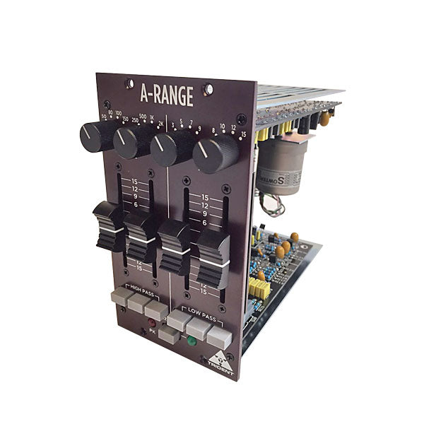
Extended Function

If you have a Radial Work horse™ or compatible rack, you can send the output of the A-Range® to the rack’s internal mix buss. To do this, locate jumper J1 on the main circuit board near the edge connector. Move the jumper onto the two pins nearest R53.

Technical Specifications

Input impedance: 10kohm balanced

Common mode rejection: 70dB

Equivalent input noise: -85dBu (unweighted, no boost or cut)

Distortion: 0.05% (+4dBu output, 1kHz)

Frequency response: 20Hz to 20kHz (-1dB)

Boost / Cut range: +/-15dB (variable)

Filter Q value: 1.3 (1 octave)

Maximum input level: +22dBu

Max output before clip: +28dBu (10k load)

Nominal output level: +4dBu (electronically balanced)

Output impedance: 100 ohm

Output noise floor: -85dBu (typical, unweighted)

Peak LED threshold: +16dBu

I/O connections XLR: pin 2 +, pin 3 -, pin 1 ground

Current requirement: 130mA (maximum) per rail

Check out our featured projects

SVG Background

FAQS

Have a question?

Our Customer support is available Monday to Friday, 8 - 10 est. Contact us with your questions or to get a quote request.